
Guide to Transmission Tower Types and Their Structural Roles
TL;DR: Each transmission tower type exists because of the specific loads it must carry, not because of preference or appearance. Understanding suspension, tension, terminal and transposition towers is essential before you can read a design drawing or build a structural model.
Transmission Tower Types: What Each One Does and the Loads It Carries
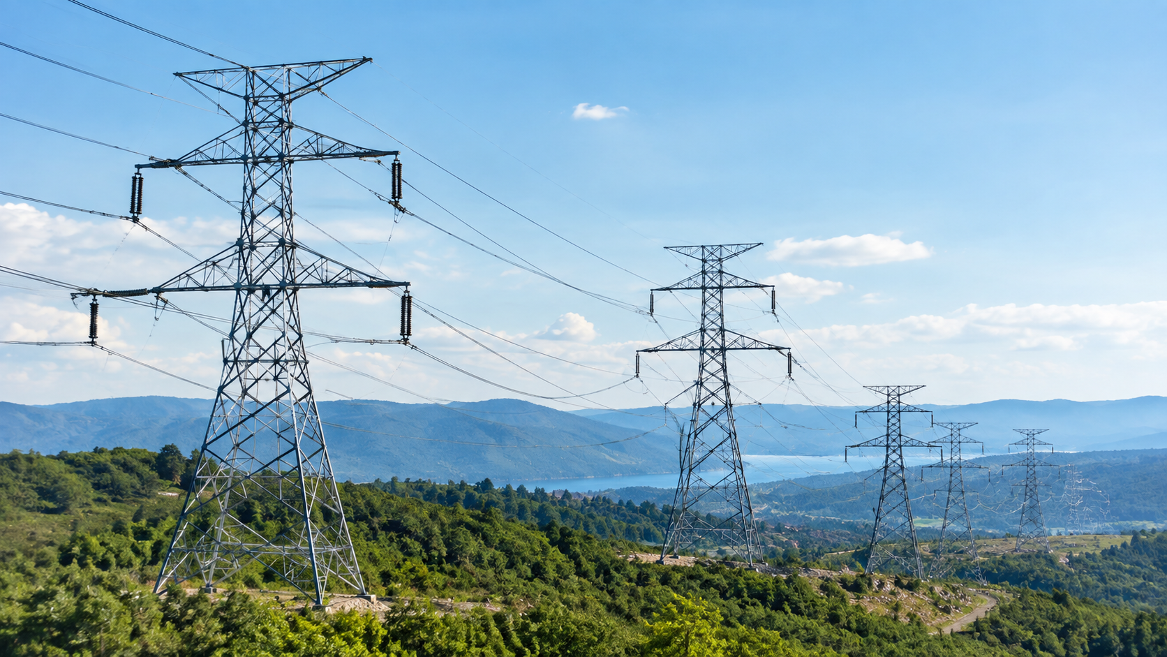
If you're new to transmission line work, tower drawings can look like a foreign language. You see labels like "suspension," "angle," or "dead-end," but nobody explains why those names matter or what they tell you about the structure.
The problem isn't a lack of information. It's that most resources jump straight into complex load cases without first explaining why each tower type exists.
Once you understand that a tower's structural form follows directly from its duty on the line, the vocabulary clicks into place.
Why Tower Type Follows From Duty, Not Preference
A transmission line isn't a single structure. It's a system of conductors, insulators and towers working together across kilometres of terrain. Each tower in that system faces different mechanical demands depending on where it sits and what the line does at that point.
The duty determines the tower type. A tower holding conductors in a straight run carries different loads than one at a corner or at the line's end. Designers don't choose tower types for appearance. They match the structure to the forces it must resist.
This means you can often predict a tower's type by looking at where it sits in the line. A straight section calls for lighter structures. A sharp angle or termination point demands something heavier.
Understanding this principle is the first step to reading any transmission line design.
Suspension Towers
Suspension towers are the most common structures on most transmission lines. They support conductors in a straight or near-straight run, with the conductor hanging from suspension insulators attached below the crossarm.
The primary loads on a suspension tower are:
Vertical loads from the weight of conductors, insulators and any ice accumulation
Transverse loads from wind pressure on the conductors and the tower itself
Minimal longitudinal loads under normal conditions, since conductor tension is roughly balanced on either side
Because longitudinal loads are low, suspension towers can be lighter and less expensive than other types. However, they're designed assuming both spans remain intact. If a conductor breaks on one side, the unbalanced tension can overstress the tower. Some designs include "anti-cascading" features to limit damage if this happens.
In a line with gentle terrain and few direction changes, suspension towers may make up 80% or more of the structures.
Tension and Angle Towers
Tension towers, sometimes called angle towers or strain towers, are used where the line changes direction or where the design requires a structure that can resist unbalanced longitudinal loads.
At a direction change, the conductor pulls on the tower from two different angles. The vector sum of those tensions creates a resultant force that the tower must resist. The sharper the angle, the greater the resultant load.
Tension towers handle:
High longitudinal loads from conductor tension on both sides
Transverse loads from the resultant of the angle and from the wind
Vertical loads from the conductor and ice weight
Strain insulators are used instead of suspension insulators. The conductor is terminated on one side and connected on the other, allowing the tower to isolate spans and resist tension directly.
Angle towers are classified by the deviation angle they can accommodate. A small-angle tower might handle turns of 0 to 15 degrees. A medium-angle tower might handle 15 to 30 degrees. A large-angle tower handles sharper turns. Designers select the appropriate class based on the survey data for each tower location.
Terminal and Dead-End Towers
Terminal towers, also called dead-end towers, are found at the start and end of a transmission line or at major transition points such as substations.
Unlike suspension towers, which rely on balanced conductor tension, terminal towers must resist the full conductor tension on one side with no balancing tension on the other. This makes them the heaviest structures on the line.
Terminal towers carry:
Maximum longitudinal loads equal to the full tension of all conductors and ground wires
Vertical loads from the weight of all attached hardware and conductors
Transverse loads from wind on the structure
They use strain insulators and heavy anchor systems. Because they resist such high loads, they're often the most expensive towers per unit, but they're essential for line integrity.
You'll also find dead-end towers mid-line where designers want to isolate sections for maintenance, limit cascade failure, or accommodate major changes in conductor type or voltage.
Transposition Towers
Transposition towers rotate the phase positions of the three conductors along the line. This balances the line's electrical characteristics and reduces interference.
From a structural standpoint, transposition towers often combine the duties of tension towers while adding complexity to crossarm geometry. The conductor must be terminated on one side, physically moved to a different phase position, and reconnected on the other.
Transposition towers carry loads similar to those of tension towers, including longitudinal tension from strain insulators and transverse loads from the angle created during phase rotation.
On long transmission lines, transposition is typically done at one or two points. Each transposition tower must be designed for the specific arrangement required at that location.
Lattice vs Monopole vs Guyed Configurations
Tower type (suspension, tension, terminal) describes the duty. Configuration describes the physical form that delivers the required strength and stiffness.
Lattice towers use steel angle sections bolted together into a three-dimensional truss. They're efficient for high loads and long spans, and their open structure reduces wind load. Most high-voltage transmission towers worldwide are lattice structures.
Monopole towers are single tubular or tapered steel poles. They have a smaller footprint and are often used in urban areas or where visual impact matters. They can serve as suspension, tension or terminal structures, but they're generally heavier for the same capacity as lattice towers.
Guyed towers use a central mast supported by tensioned cables anchored to the ground. The guys carry much of the load, allowing the mast itself to be lighter. Guyed structures are common at very high voltages or for tall structures, but they require more land for anchor points.
Choosing between these configurations depends on voltage, span length, terrain, land availability and local preferences. The structural duty determines the loads; the configuration determines how those loads are resisted.
How Each Type Is Represented in a Structural Model
When you model a transmission tower in software such as PLS-TOWER, the tower type directly affects how you define loads and constraints.
Suspension towers are modelled with vertical and transverse loads applied at the conductor attachment points. Longitudinal loads are typically small unless you're analysing broken-wire cases.
Tension and angle towers require you to input the deviation angle and the full conductor tension on each side. The software calculates the resultant forces.
Terminal towers are modelled with full conductor tension applied on one side and no balancing load on the other.
Transposition towers combine tension modelling with the specific phase arrangement at that location.
The model also captures the configuration. Lattice towers are built from individual members with defined sections and connections. Monopoles are modelled as single tapered elements. Guyed structures include the mast, guys and anchor points.
Accurate modelling depends on understanding what each tower type must resist. If you misclassify a tower's duty, the loads in your model won't match reality.
Reading a Tower Type Off a Design Drawing
On a plan-and-profile drawing or a tower schedule, each structure is labelled with a designation that tells you its type and class.
Common conventions include:
S or SUS for suspension
A for angle, sometimes with a number indicating the angle range
T or DE for terminal or dead-end
TR for transposition
The drawing will also show the configuration (e.g., lattice or monopole) and the height class. Combined with the survey data, these labels tell you what loads the tower is designed to resist and what hardware to expect at that location.
If you can read these designations, you can follow a line from end to end and understand the structural logic at each point.
Ready to Model These Structures Yourself?
Northern Star Power Line Consultancy runs a PLS-TOWER course that teaches engineers to model and optimise exactly these tower types.
The training covers load cases, member design and everything you need to move from reading drawings to building accurate structural models.
Questions Engineers Ask About Transmission Tower Types
What determines whether a tower is lattice, monopole or guyed?
The choice depends on voltage, span length, available land and local requirements. Lattice towers are common for high loads and long spans. Monopoles suit urban areas with limited space. Guyed structures work where land is available for anchor points, and height is critical.
Why are suspension towers lighter than tension towers?
Suspension towers rely on balanced conductor tension, so they carry minimal longitudinal load under normal conditions. Tension towers must resist unbalanced forces at direction changes, requiring heavier members and foundations.
How often are transposition towers used on a line?
Most lines transpose once or twice over their length. The exact locations depend on line length, electrical requirements and survey constraints.
Can a suspension tower be upgraded to a tension tower?
Generally, no. The structural members and foundations are designed for the original load case. Changing duty usually requires replacing the structure entirely.
Read the Structure by Its Job
Every transmission tower type reflects the loads it must carry. Once you understand that, design drawings become much easier to interpret.
If you want to learn how these structures are modelled and checked in practice, explore Northern Star Power Line Consultancy's PLS-TOWER training.
